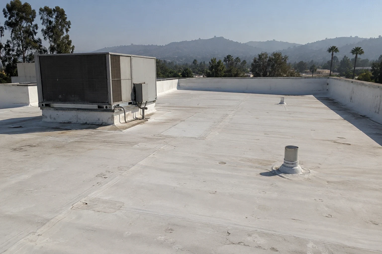
Commercial Roof Insulation and Cover Board in Tracy, CA
Commercial Roofing Services
Plan Tracy roof insulation or cover-board work by assembly, moisture findings, attachment method, drainage, and owner-approved scope limits.
Plan Tracy roof insulation or cover-board work by assembly, moisture findings, attachment method, drainage, and owner-approved scope limits.
Insulation work changes roof thickness, transitions, drainage, and fastening. Before adding or replacing a layer on a Tracy commercial building, identify the existing assembly, locate any wet or damaged areas, and confirm what the owner expects the project to solve. Cover board may serve as a substrate, protection layer, or component of a specified assembly, but its use depends on the system detail. A proposal should identify where insulation is removed, retained, or added and how the new work meets curbs, drains, parapets, and edge metal.
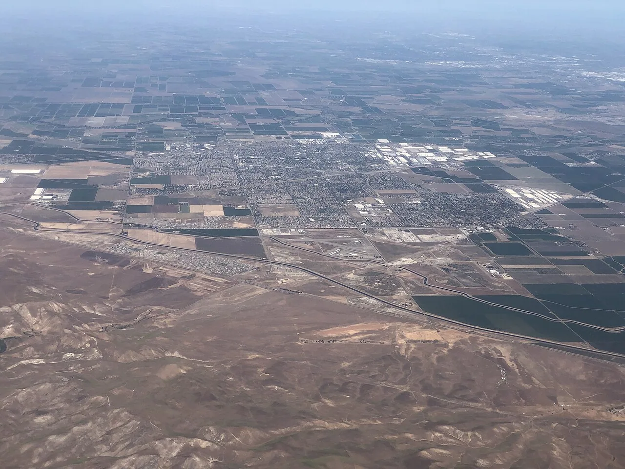
Tracy planning materials distinguish Downtown from industrial and employment areas. That land-use context does not identify a building's insulation or justify a thickness without project-specific review. Review the building requirements and assembly records with the responsible design professional. Start with a condition inspection and any approved moisture verification.
Gather plans, prior submittals, warranty documents, repair tickets, and any core or test results. Record membrane type, insulation layers, cover board, vapor retarder, deck, and attachment details where evidence exists. Separate confirmed layers from assumptions. An exposed edge or opening may reveal a different build-up than the record, so the scope should state how that discovery will be handled. Do not design a new assembly from a surface photograph alone.
Confirm the selected materials are permitted by the membrane manufacturer and project specifications. Check compatibility with adhesive, fasteners, plates, primers, and existing substrates. A cover board designation alone does not answer compressive, moisture, fire, or wind-design requirements. Identify the applicable product and thickness, installation pattern, and approval source in the submittal before procurement. Include transition pieces where the new height meets existing work.
Thermal targets and code details belong in the project design. The contractor should not select a board thickness from a generic recommendation without checking the building use, existing layers, vapor control, deck, and specified energy or fire requirements. If an existing roof remains below new insulation, identify whether it is a permitted substrate and how trapped moisture or discontinuous vapor layers will be handled. Record any design question for the responsible professional before material is ordered.
Delivery and storage also affect the installed assembly. Keep boards dry, protected, and supported according to product instructions. Reject damaged edges or wet material rather than cover it. Stagger joints where the design requires and avoid leaving open gaps at perimeters, curbs, or changes in plane. The foreman should compare installed thickness and fastening with the approved detail at hold points before the next layer hides the work.
Keep the approved submittal with the field checklist so substitutions are reviewed before installation, not after concealed work is complete.
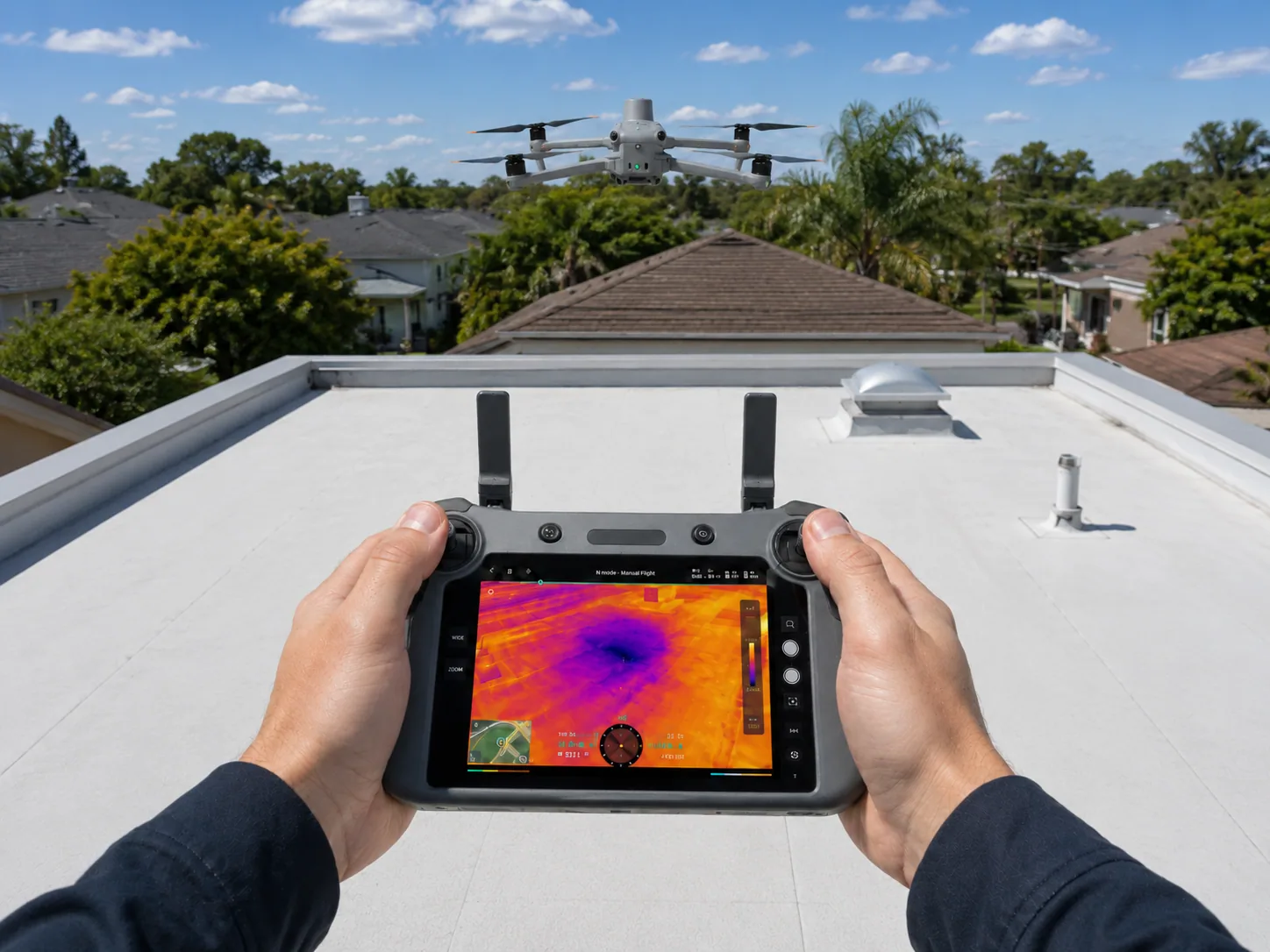
Moisture mapping can help prioritize investigation, but an infrared anomaly or stain is not proof that insulation is wet. Compare visible conditions, records, and test results. If the owner authorizes an opening, label its location on the roof plan, record each exposed layer, and photograph the condition before covering it. Mark areas that could not be tested and identify what additional access would resolve the question. Do not carry an unverified finding into a confirmed removal quantity.
The Northeast Industrial PUD is a roughly 870-acre planning area at Tracy's northeast corner. For an industrial property with multiple structures, track test results and insulation quantities by building and roof zone. A moisture survey can help identify candidate locations for approved checks, and a condition report can distinguish observed anomalies from verified wet material. That record supports a repair or replacement decision without overstating the evidence.
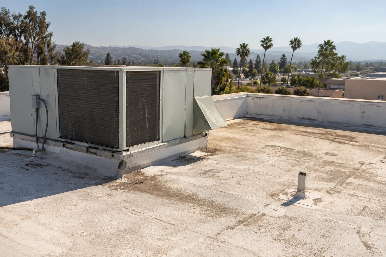
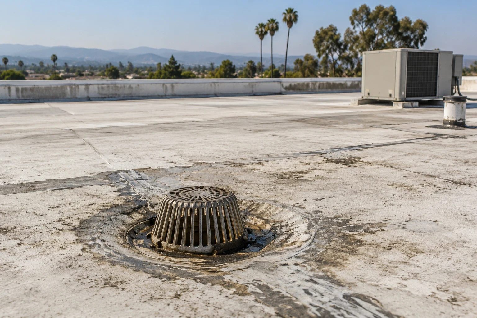
Added insulation can change finished elevation, drain bowl relationships, scupper heights, curb clearances, and edge-metal geometry. The design should show the new slope and drainage path rather than rely on a field crew to improvise around existing details. Confirm that overflow locations remain functional and that terminations do not create a backwater point. Where taper is specified, coordinate board layout with outlets, sumps, and rooftop obstructions.
Tracy's planning materials identify an I-205 Corridor area with commercial uses near Grant Line Road and I-205, but that geography does not determine a building's drainage design. At a facility in the I-205 Corridor, use actual roof plans and approved details. A drain review can record existing conditions; it cannot replace a design revision when the finished assembly height changes.
The attachment method depends on the deck, existing layers, assembly design, wind criteria, and manufacturer requirements. A drawing should identify board orientation, fastener or adhesive pattern, perimeter and corner zones where applicable, and how the membrane is secured. Do not infer a fastening schedule from another building or a general exposure statement. Verify deck condition and pull-test requirements if the approved design calls for them.
Tracy lists wind exposure C and directs design wind speed to applicable maps and risk category. That city criterion does not confirm the current deck or existing fastener capacity. Provide the project's wind design and specified assembly to the installing team. If records are incomplete or field conditions differ, pause at the scope limit and obtain direction. For a TPO assembly or EPDM system, follow the current approved detail rather than mixing components based on appearance.
Write the work in measurable units and zone boundaries. State demolition depth, insulation type and thickness, cover board, attachment, membrane, edge transitions, drain work, and disposal where included. List areas that remain, conditions that trigger a change request, and whether insulation replacement is provisional pending opening. Include protection for occupants, equipment, and interior operations. If a discovered layer or deck condition changes the assembly, the crew should stop at the approved limit and document it before proceeding.
Closeout should identify installed products, lot or batch information when required, photographs of concealed layers and transitions, test results, and any remaining open items. The replacement scope should coordinate insulation with the full roof system. Keep the record attached to the asset plan so future maintenance can see actual thickness and details rather than a generic note that the roof was reroofed.
Sequence penetrations and rooftop equipment work so new insulation is not left exposed to weather or traffic longer than the approved plan allows. Mark temporary protection and inspect it after each shift. Before final membrane placement, verify that drains remain accessible and that the new surface has a continuous path to the designed outlets. These checks should be documented by zone, not summarized as a single roof-wide signoff.
An infrared scan can identify patterns for investigation, but it cannot confirm wet material by itself. Weather and assembly conditions may create similar anomalies. Use an owner-approved verification method before counting material for removal.
No. The assembly, substrate, deck, materials, attachment, and manufacturer or design requirements must be confirmed. Records and field conditions should match the specified detail.
It can change elevations and clearances. Review drains, scuppers, curbs, parapets, and metal terminations in the assembly design before installation.
That exposure classification is a city design criterion, not a fastening schedule. The project design, applicable wind maps, risk category, and actual deck conditions determine the approved attachment.
A record of installed layers and products, concealed-condition photographs, approved changes, test results, and unresolved areas, all tied to building and roof-zone identifiers.